PowerLabs Induction Heating!
Introduction:
The concept of heating without any physical contact: induction heating, has been around for over 40 years and finds use in almost every industry where metals are used, be it in alloying, metal forming, tempering, hot working or shrink fitting. Being able to heat materials at speeds unheard off through conventional means, with pinpoint accuracy and heating efficiencies above 90%, and doing so without any physical contact brings numerous advantages to production; there is no risk of contamination, a smaller setup with less insulation is required, and the entire process becomes much more environmentally friendly, just to name a few. The basic principle behind heating by induction is that a very strong rapidly alternating magnetic field will induce eddy currents on any conductive material placed in the vicinity of that field. These eddy currents than heat the metal by induction. The amount of heating will depend on the field strength (and thus the amount of power running through the heating coil and how far it is from the material being heated), how quickly the field is changing (the heating coil power supply frequency), and the degree of coupling between the coil and what is being heated (how close the objects are to one another, what their geometry is). Maximum temperature achieved will depend on how much power is going into the heating process and how much power radiates out of it. Higher powers with larger degrees of coupling and high frequencies will heat up materials faster, but higher frequencies will also cause heating to be shallow. For the sake of curiosity, PowerLabs attempted to construct a simple induction heating machine to demonstrate the concept of heating by induction.
First attempt: Spark gap switched 1kW induction heater:
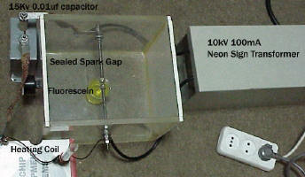
To the left the first heater is seen. The design was entirely made up to fit whatever parts I had left over from other projects and as such is not optimized in any way. It resembles the first induction heaters ever created in that the high magnitude alternating current pulses are created on it by means of a spark gap switched RCL circuit, no different from a Tesla Coil. The power supply is a 10kV 100mA (1000W) Neon Sign Transformer which charges up a 15kV 0.01uF capacitor over 120 times per second. Once the capacitor has reached a charge voltage greater than the spark gap break down voltage the gap fires and discharges the capacitor through the heating coil; 15 turns of AWG 10 modified polyurethane insulated copper wire (rated for 180C). The capacitor/coil/spark gap combo form an RCL circuit of very low impedance which causes a very high surge current to oscillate at several hundred KHZ through the coil. This current causes a powerful alternating magnetic field to form inside the test tube the coil is wound around, and this field in turn heats our test specimen: 50 grams of coarse (#80) iron powder. The spark gap was sealed inside a box to dampen the very loud noise it makes as it fires repeatedly, and a small beaker filled with 50mL of fluorescein was placed inside the box for aesthetic purposes, as fluorescein fluoresces under the intense UV light of the gap.
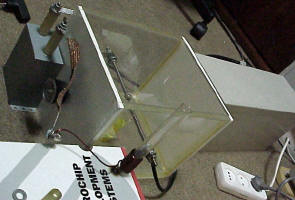
Here the entire setup can be seen, along with the heating coil. Notice the burn mark on the box that was serving as a support for the coil. Several tests were performed, and these usually ended up with the coil insulation burning right off due to ohmic heating within the coil (C.A. 200C). The glass was undamaged though, despite the fact that the iron reached over 900C.
>>>PSPICE CIRCUIT SIMULATION AND SCHEMATICS TO COME!<<<
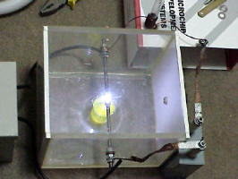
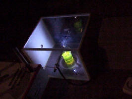
Here the system can be seen in action. Notice how the fluorescein glows strongly from the powerful UVA and UVB emissions of the spark gap. If the gap box was to be opened, ear protection would have to be worn around the device, but with a sealed gap nothing but a high pitched whine could be heard.
Results
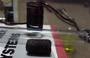
The system performed properly and was able to heat the small iron powder load to orange heat within a few tens of seconds. On the picture to the left a sintered iron slug shaped like the test tube that held it originally can be seen, with the burnt coil on the background. Overall this experiment was a success, as surprisingly enough the capacitor and transformer used did not get damaged by the high peak currents and high frequency electricity involved in the project. Efficiency could be greatly improved by using a higher gauge heating coil, a better switching method (hydrogen thyrathon, high speed SCR stack, or a multi section spark gap such as the one used on my Tesla Coils) and a larger capacitor, resulting in less resistive losses and a lower frequency which would penetrate the specimen better and lead to more uniform heating.
Solid State Induction Heating:

Modern induction heaters normally utilize a high frequency MOSFET or transistor powered inverter to produce the high current oscillating electricity that powers the heating coil. SCRs are also used but to the purpose of chopping up the current into a series of pulses. In this particular setup the SCR was merely substituting the spark gap on an RCL circuit. This brings about the advantage of higher switching efficiency (95 – 98% as compared to 50 – 70% for a spark gap) but at the same time blocks off the entire oscillation from the first voltage reversal onwards since SCRs are monopolar devices. This is undesirable since it shunts power in a very inefficient and damaging way, but was attempted nonetheless because by using a lower voltage a Ballast could be used to get more power into the system than the 1kW neon transformer could provide, and also because the components available were over rated enough for the application that no damage should have occurred.. In this set up mains current (110V) is ballasted by a shorted out microwave oven transformer and rectified by a full wave bridge rectifier, charging up a 3150uF electrolytic capacitor bank (again a very unwise choice since being inherently monopolar devices electrolytic capacitors will heat up during any oscillation that occurs on discharging through an RCL circuit, but again used because of the over rating factor and the fact that the SCR by itself was already going to cut off the oscillation)) to 155V, at almost 3000W.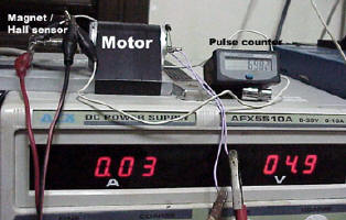
The capacitor bank dumps almost 40J on the heating coil through the SCR at a pulse rate selected by a timer. The timer was a hall effect probe near a multi pole spinning magnet, and pulse rate could be adjusted by controlling motor speed, and read out of a counter. SCR trigger supply was a second power PSU set for 5V.
As with the first heater, a small iron powder batch was heated by running the machine at maximum power for a set period of time. The following observations were made:
1- The power supply fed 16A at 155V to the capacitor bank. This results in a power consumption of nearly 2500W. That is enough to cycle the bank at nearly 66pulses per second. Setting higher pulse rates on the timer would result in a lower energy per pulse, up to the point where the SCR failed to shut off and a continuous discharge occurred.
2- By discharging a very large amount of energy into the heating coil the machine made a lot more noise and the coil/heating batch assembly jumped around a lot. There was significant coil deformation also due to the high magnetic forces involved.
3- Back EMF kept on blowing my power supply fuses, so runs greater than 3 seconds could not be achieved. Even than, after 3 seconds the iron batch had become warm enough that it could not be held.
A future device could be constructed which would use a proper timer (perhaps a 555IC with a transistor controlling the gate of the SCR) and switch rectified and filtered mains current directly onto the coil without an RCL circuit; this would be more efficient and yield better results. However since at the time I have no need for such a device, I have stopped pursuing the subject. I hope my experiences have been of use to some.
Please Donate to PowerLabs so I can continue to fund more experiments!
© 2022 Copyright by Sam Barros. All rights reserved.
Removing any material from this site for display without consent from its author consists in an infringement of international copyright laws and can result in fines up to $50000 plus legal costs per infringement.

