PowerLabs Wimshurst Generator Page
The Wimshurst machine was invented by J. Wimshurst in the 1880’s and was the most famous electrostatic machine of the nineteenth century, before the Van De Graf generator came along. Electrostatic machines such as this one remained popular throughout the 19th and 20th century as a means of generating very high voltages which induction coils just couldn’t stand due to their limited insulation.
In this particular machine the disks are 50Cm in diameter, 3mm thick, and have 40 sectors each, spaced out by 2.5cm, implying that, in theory, the generator should be capable of producing sparks nearing 300Kilovolts (details lower in the page).
If these fantastic attributes do not explain my eagerness to repair this fantastic machine, than perhaps It may be interesting to note that a similar machine (same size, similar design, but using an electric motor to spin the disks) costs 2700dollars at PV scientific instruments!
The total reconstruction took a week to complete, with over 30 work hours going into it. Here is a summary of the work that was done:
Stage 1: Preparations, cleaning and degreasing (3 hours).
1- Documented the original state of the machine with photographs, from different angles and perspectives (still to be developed).
2- Did a general analysis so as to determine the best restoration process.
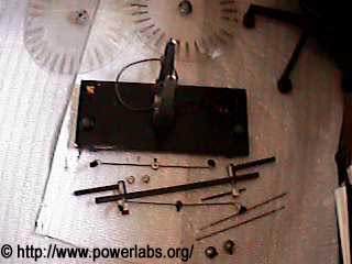
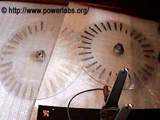
3- Took the entire machine apart, down to the last bolt (as seen on the pictures below).
4- Cleaned the disks with soap water (there was solidified dust residue on them, presumably from electrostatic attraction), and removed paint residue with a blade.
5- Thoroughly degreased the moving parts
6- Polished metal conductors so as to remove oxides.
7- Cleaned wooden base and removed paint residue.
8- Removed plastic bits from pickup points (there were only two), and cotton from neutralizers (I still don’t know what those things were doing there, but they sure as hell don’t belong in that place!!!)


Stage 2: Minor Repairs (2 hours, non-stop).
9- Replaced the leyden jar interconnecting wire that ran through the underside of the base for a thicker one, and had it insulated.
10- Increased angle on both nut washers in the spark gap base enclosure, so as to avoid having the spark gap move as it did before.
11- Straightened the wires for the neutralizers.
12- Replaced old & ripped leather belts for new ones, cut and joined to size.
Stage 3: Making Replacement parts (3 days work, over 25 hours total).
13- Built a pair of new Leyden Jars for the machine (the old ones were missing) See picture on the left… The Jars are 31.5 cm tall, 4cm dia, 1.5cm thick white PVC pipes with heavy duty aluminum tape over them, and aluminum foil inside them. The bottom terminal can be seen on the picture. The top terminal is connected to the discharge terminals through 6mm diameter copper tubes. Each jar is rated at 180pF capacitance, and they both amount to a total 90pF (they are in series), at approximately 200Kilovolts. (interesting fact: When fully charged, the system holds approximately 2Joules of energy! It should be possible to calculate the efficiency of mechanical-electrical energy conversion in the system by counting how many sparks it makes in a second, and how much voltage it develops in the capacitors before it discharges by the spark length). More on that later…
14- Had the silver cup on the electrode terminal holder removed, drilled a 6cm diameter hole through the holder, and another hole on the insulator bar that held the electrodes. Than I bent a 6mm copper tube into an “L” shape, inserted one side into the leyden jar, the other through the insulator bar, and had it bent once again at 90 Degrees. Finally I passed another tube through the electrode holder, and soldered both of them together, so as to form a “U” shaped charge pickup brush holder… Sounds complicated? Just imagine how long it took to make this!
15- Soldered charge pickup brushed onto charge pickup brush holders and onto charge neutralizers.
16- Cut 85 pieces of 0.1mm copper foil for the sectors in the machine (by hand!!!). I cut an extra 5 just in case some didn’t come out perfect. This took over 4 hours and was incredibly tedious… The reason why copper was chosen is that it has a better wear resistance than aluminum. The foil thickness used here is also considerably greater than the one the machine originally used. This should ensure that it lasts long.
17- Glued all 80 copper foil sections onto the disks, using cyanocrylate “super” glue.
18- Polished copper foil sections
19- Re-assembled the now finished machine.
Here is a picture of the now finished Wimshurst (standing on top of the PowerLabs design and assembly table), ready to be run:
How it works:
(Not quite completed, I’ll be adding diagrams soon).
It is a known quantum effect that when two different conducting metals touch each other there is a small current transfer between the two (because no two materials have the same number of electrons in their atoms and electron bonding forces are also different in different materials). This happens when the sectors in the disk pass through one of the charge neutralizers. On doing so, the sector becomes charged, and, as it passes by a sector in the other side of the disk it induces an equal but opposite charge on that sector. Now lets assume that the front disk has a positive charge on its sectors; than, by definition as it spins it will start to induce a negative charge on the back disk. The same thing happens to the lower part of the disks, but in reverse, so when a sector passes by the neutralizer bar it becomes neutral and therefore ready to be charged again. This sets up low opposite charges on the top and bottom and high equal charges on the sides. These high charges are than picked up and transferred to the leyden jars, which in their turn are connected to the discharge terminals. When the voltage is high enough across the terminals a spark occurs and the cycle restarts.
Note that when the machine starts spinning it can become charged either way (+- or -+).
Machine Limitations:
The practical voltage output limitations of a Wimshurst machine operating at standard atmospheric conditions are two: First as the voltage increases partial ionization (corona) losses will become more and more pronounced, and as they start to drain more and more power from the system, the voltage will drop. There are two solutions to this: first any potential partial discharge point must be eliminated. This means filing down any sharp edges, choosing wide diameter conductors, making wire bends blunt and broad, and insulating any exposed conductors which are potential sources of corona emission. Secondly, no matter what you do, there will always be some corona emission (specially visible around charge pickups and disk sectors). Hence, the system must be able to output enough current so as to overcome those losses and reach it’s full voltage potential. The final barrier for a Wimshurst machine is to make sparks that are slightly longer than the distance of all the total spacing between a third of it’s disks (between the pickups and the neutralizers, assuming those are set at 60degrees from the horizontal, for maximum efficiency). It ends up slightly longer than this distance because single long sparks happen more readily than several shorter sparks. However, when this limit is reached the voltage simply becomes so high that the generator discharges itself through the disk sectors, which is bad for the insulator.
On a dry day, this machine should be able to produce sparks in excess of 20cm (8″). As of the time this page was written, the longest spark ever obtained from it was 16cm. Sparks that long require very high rotation speeds and make a loud snapping sound.
Interesting facts: Being shocked by this machine is not too different from getting zapped by a stun gun, and it will in fact make the spark’s strike points go numb for a while.
The largest Wimshurst machine ever built had two varnished glass plates 2.13m in diameter and 9.8mm thick. It was designed to produce 76cm long sparks. It was built by J. Wimshurst himself.
Here are two pictures from a smaller machine I recently repaired. This one has disks 25cm in diameter and uses 56 sectors. All I had to do here was replace a few sectors, replace the belt, lubricate moving parts, and make new charge pickups. When finished, this machine was able to make 7cm long sparks, one centimeter longer than what the manual said to be its limit!


Please Donate to PowerLabs so I can continue to fund more experiments!
© 2022 Copyright by Sam Barros. All rights reserved.
Removing any material from this site for display without consent from its author consists in an infringement of international copyright laws and can result in fines up to $50000 plus legal costs per infringement.

