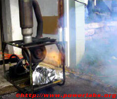
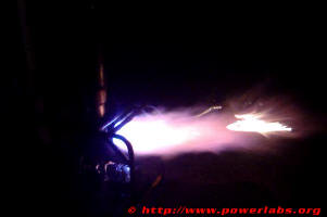
The PowerLabs Turbine!
Project Introduction:
 For as long as I can remember I have had a fascination with engines; it was largely because of this fascination that I picked Mechanical Engineering as my current major in University. As far as engines go, there is nothing quite as impressive as a turbine: the incredible power-weight ratio they have, the awesome high pitched whine as they spool up to hundreds of thousands of RPM and of course the supersonic exhaust and the implications it had in revolutionizing the way we fly today. Although the precision involved in the making and balancing of centrifugal compressors and turbine blades is well beyond the realm of amateur science (for now, anyways), with some good welding skills and a few conventional parts converting a commercial turbocharger into a self contained home built turbine becomes a simple task… My friend Joe Studinger, who is also a Mechanical Engineer at Michigan Technological University shares my passion for turbines and has helped me from the start: both financially and at the machine shop in this project. His help was invaluable in obtaining and creating parts and on getting us both engulfed in a fireball and losing hair as we attempted -and finally succeeded- to start up the home made jet for the first time.
On this page you will see how we went about converting a turbocharger into a homebuilt turbine.
DISCLAIMER: This is a very dangerous project. Making a turbine deals with handling compressed highly flammable gases and liquids, and having them plumbed into a source of ignition. Aside from the fire hazard, the turbine itself has no RPM control whatsoever and can very easily overspeed and explode into lethal shrapnel. Projects such as these should only be attempted by trained professionals.
Project Description and Goals:
 The initial goal of this project was to construct a reliable turbine from a diesel truck turbocharger. This essentially entails the creation of a means to deliver and ignite fuel into a custom made combustion chamber, creating a high pressure oil delivery system for the turbo shaft and bearings, a thrust nozzle and all other associated equipment required to safely and reliably convert the turbo into a self sustaining turbine. Although we are still working on the “safely and reliably” (the safety and reliability of anything removed from a junkyard and made to spin at 60000+RPM as it consumes and entire tank of propane gas in a couple minutes is questionable at best), now that it works the new project goal will be to increase its efficiency, evaluate the thrust, and possible utilize it to propel a lightweight craft.
Turbo:
 Whereas most amateur turbine projects employ small turbochargers removed from car engines, for this project we are using one of the largest turbochargers you can find anywhere. This Garrett T18A40 was removed from a turbo diesel V8 semi truck and weights around 50 pounds. The large size of this turbo presented special challenges as far as designing a combustion chamber and fuel delivery system large enough to feed it, and devising an oil delivery system with enough flow to keep its shaft and bearing properly oiled and cool at all times.
 Although it might have been desirable to start off with a smaller turbo, this one was available and in working condition, which was what prompted us to start the project in the first place. Its size should also be advantageous should we decide to power something with it.
 When the turbo was first obtained it was covered with thick carbon sooth in the front and rust on the back. It was impossible to touch it without getting one’s hands black with dirt. The first step in this project was to completely clean out the engine and remove all rust, carbon sooth and old lubricating oil from it. Opening up the turbo also gave us a chance to inspect it for any kind of damage which might compromise the safety of the project.
Carbon sooth was removed using a petrol based industrial parts cleaner, rust was removed using an air grinder and a wire brush and most of the old oil was removed by flooding the bearing and shaft housing with light lubricant oil and flushing it out with high pressure air repeatedly. The turbo housing was not opened so as to preserve the original seal since everything seems to run fine as it is (no shaft play whatsoever).
Combustion Chamber, flame tube and fuel delivery:
 Vehicle turbochargers work by harnessing the power of hot gases expanding out from the engine exhaust to turn a turbine which in turn drives a compressor through a common shaft. The compressor pumps high pressure air into the engine which boosts its power output and makes more hot compressed gases available to the turbine, essentially providing nearly unlimited amounts of power boost until the turbocharger waste gate or blow off valve opens and bleeds off excess pressure into the atmosphere or back into the intake. Essentially, in order to convert a turbocharger into a self sustaining turbine all that is needed is to provide it with another source of hot gases to drive the turbine from.
By attaching a combustion chamber to the turbine and feeding it with air from the turbo compressor the turbine is able to burn fuel and drive itself to extremely high RPMs, being limited essentially only by how much fuel can be combusted in the chamber and how quickly the blades can spin before they catastrophically fail and fly apart.
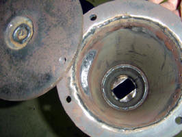
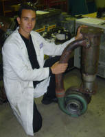 Turbine combustion chambers are very intricate designs which involve a deep knowledge of thermodynamics, flame and combustion dynamics, heat transfer, materials science and fuel chemistry. Through computer modeling it is possible to optimize these factors so as to achieve very high performance in a package that is both lightweight and reliable. For our amateur purposes weight and reliability are secondary to price and ease of construction; as such, our challenge was to approximate the required parameters and adapt the desired design to fit existing materials. The final combustion chamber design is welded from exhaust pipes and scrap iron and measures 6 x 16 inches; the length and diameter being determined mainly by the spray pattern of the nozzle used. Liquid propane gas is injected from an oil burner furnace nozzle through the top of the combustion chamber, its pressure regulated by the gas tank itself. We found that even at the maximum setting the propane tank simply couldn’t keep up with the enormous fuel consumption of the turbine, and our solution was to tip the propane tank upside down so as to make liquid propane flow into the nozzle. The liquid propane is a lot denser and fueled the turbine flawlessly. The unfortunate side effect of flowing liquid propane out of the tank is that even a relatively large 10lb tank is completely consumed in a matter of minutes through this fashion. Also, the tank becomes very cold as it empties and as the pressure drops the combustion in the chamber becomes unstable and the turbine sputters a lot (this is mainly a factor when the tank is nearly empty).
 A few factors worth noting are the offset compressor input for turbulence and a swirling airflow, and the non optimal turbine combustion chamber mating at the bottom of the chamber; the round_into_rectangular transition creates horrendous turbulence in an area of rapid gas flow, but is unfortunately unavoidable due to the turbine design.
The flame tube is said to be a very critical part of any combustion chamber design. Others have spent countless hours trying to figure out a “perfect” pattern to arrange the holes so as to maximize combustion efficiency. We found that stuffing a 3″ diameter x 16″ 305 stainless steel perforated mesh tube securely into the chamber worked very well; the mesh becomes yellow hot after a couple of seconds and allows the combustion to self-sustain. Details on the mesh are as follows: Type 304 Stainless Steel Perforated Sheet, .1875″ Hole Dia, 51% Open Area, 20 Ga. Price was the main deciding factor on this.
Ignition System and Start Up:
 Initially the idea was to use an automotive spark plug to ignite the fuel inside the turbine. A simple 555/2N3055 ignition coil based high voltage generator would suffice for that. We didn’t get it done in time, so instead we opted to use a can of Ethyl Ether carburetor starter, spraying the flaming liquid right into the intake with the turbine spooled up and propane flowing into the chamber. It resulted in Joe and I being engulfed by flames, me burning hair off my arm and getting blisters on my hand, a lighter being melted, hoses burned and the test stand catching on fire multiple times. It did work, but a proper ignition system was badly needed. Currently the turbine is started through a barbecue piezo-electric igniter; a porcelain insulator is epoxied into the combustion chamber with high temperature epoxy and a high voltage wire is run from the insulator to the wall of the combustion chamber. The turbine is spooled up with a leaf blower, propane gas is allowed to flow into the combustion chamber and the blower is then removed while the starter sparks inside the combustion chamber. As the turbine spools down an optimal air/fuel ratio mixture occurs inside the chamber and it ignites with a loud backfire. The leaf blower is then brought back into the turbine, gas flow is increased, and as soon as the turbine is heard spooling the leaf blower can be turned off and it will self sustain.
For fellow experimenters: I find that Dermoplast� Anesthetic pain relieving spray works well on superficial burns, should you decide to go the ether route. Deeper burns may require a doctor’s visit though; save on health insurance and build a proper igniter.
Oil Delivery System:
 In its original automotive application the turbocharger obtains lubricating oil directly from the engine oil delivery system, which keeps its shaft and bearings well supplied and able to run reliably for years. On a turbine the turbocharger is run at much higher RPMs and operates at higher temperatures, both of which place enormous stress on bearings and moving surfaces. Without a reliable oil delivery system the bearings are sure to burn out very quickly, particularly if the oil is not injected at a high enough pressure that it makes its way into the bearings when high loads push for destructive metal-to-metal contact. In this project a Subaru ’86 power steering pump (a vane pump) supplies 5-30 synthetic oil (we are currently looking for a lower viscosity oil) from its built in reservoir into a large diesel truck intercooler and through the turbo. Oil pressure is monitored through a gauge and can be regulated by closing a throttling valve. The design pressure for the system is >50PSI, though it is capable of pressures well over 100PSI. Copper gasket material is used to maintain seals on all mating surfaces, and a drill is used to turn the pump. The pump, cooler, gauge, valve and associated plumbing cost $80 and parts were obtained at a scrap yard and hardware stores. We are currently looking into having an oil filter installed since the turbine seems to really foul up the oil (again because of blown bearing seals).
Instrumentation:
 In order for the turbine to be safely operated a few key parameters must not be exceeded: due to the self-sustaining nature of induction fed engines, a turbine is perfectly capable of spinning itself to complete destruction when fed enough fuel. In order to prevent this the turbine is fitted with a pressure gage to monitor turbo boost pressure. Lubricating oil pressure is also monitored to ensure it remains high enough for the bearings. Soon we also plan on implementing an EGT (Exhaust Gas Temperature) probe and hopefully also a tachometer, although one needs to be designed specifically for this purpose (optical pickup with a pulse counter). Remote fuel shut off valves are employed for added safety and fuel inlet pressure will be monitored through a regulator once we begin running higher speed tests.
During our first tests we had no instrumentation whatsoever and had to listen to the turbine carefully from behind a brick wall and close the gas valve when it started getting too fast. Now we can see through the boost gage that we are not even near the maximum rated output of the compressor, and will thus start upping the throttle. Knowing how fast it is spinning is definitely an important safety asset and one we’ll hopefully be implementing by the next test run.
Nozzle and afterburner:
By itself the thrust obtained out of the back of a turbocharger is relatively small due to the low velocity of the gases leaving the large diameter outlet and dispersing quickly. With the addition of a nozzle it is possible to concentrate the exhaust gases and thus accelerate them in a fast stream which is far more efficient at producing thrust. Our initial runs were performed without a nozzle, and resulted in a compressor inlet pressure of only 5psi. We postulated that perhaps the low compressor pressure was due to lack of back pressure on the turbine end; the solution was to weld up a very quick and dirty nozzle; an 8 inch long 5.5 inch diameter pipe with a cut off funnel at the end resulting in a 3″ diameter exhaust. We also took the opportunity to weld a fuel inlet in the beginning of the nozzle to serve as afterburner; this inlet is fed from a second propane tank. It worked, and the turbine makes a LOT more noise and shakes violently with the afterburner on, but compressor pressure is still only 5psi, which indicates that our fuel supply is simply not enough to sustain higher rpms. The welds on the nozzle also blew out and allowed a lot of pressure to leak, but that’s to be expected from such a quick and dirty set up. We are currently working on a better nozzle.
Test Stand:
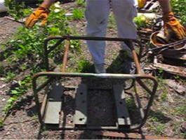
 We found this at a local junkyard; It weighs about 40 pounds and is a welded steel tubular frame from a Honda electric generator. All the turbine part fit in it perfectly and it is heavy enough that we don’t have to worry about the turbine leaving our test site.
Testing and development:
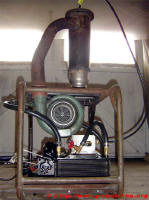 After all the parts had been gathered for the fuel and oil system and the combustion chamber was welded together the project sat gathering dust for almost a year. On Friday October 1st 2004 I called Joe and asked if he wanted to work on the turbine. On Saturday 2nd we arrived at the machine shop at 9AM and In 10 hours we cut, milled and ground brackets for the turbine and pump, drilled and threaded the injector, constructed a flame tube, welded the brackets into the test stand and bolted everything up. We ended up having to use tie wraps for the oil pump and using a drill to run it, but it worked. That night we test fired the turbine for the first time.
Joe initially thought that it would be impossible to ignite the turbine without an ignition system. I suggested that by drilling a pilot hole on the combustion chamber we could hold a torch up to the hole and get it started like that. Having seen this trick work with potato cannons, I figured it’d be a good bet. It didn’t work, so I knew it was time to take out the carburetor starter. Joe said it was too dangerous, I agreed, then took out the fire extinguishers, burn cream, and got to work. The turbine gets up to speed quickly with a leaf blower held up to the intake; then the oil pump is turned on and the gas valve is opened. Once gas starts coming out the exhaust ether is sprayed into the intake and ignited. After a second or two of spraying flaming ether into the intake the flame makes its way into the combustion chamber and the turbine backfires with an explosion. Its easy to tell it has started because the pitch of the exhaust noise changes. Once the turbine is started we let it warm up for a couple of seconds, then increase the gas flow by tipping the propane tank upside down so as to allow liquid propane to flow into the combustion chamber. The first time we did this the turbine spun up so quickly, and got going so fast we thought it was headed for immediate self destruction. On the video you can hear me yelling “KILL IT, KILL IT” to Joe so he will shut off the gas before the turbine gets going any faster. On the subsequent runs we were a lot more careful with the throttle and managed to keep the turbine running at what seemed like a more reasonable speed. The entire propane tank ran out by the end of our 3 rd run; you can see the turbine sputtering and spitting fire out of the exhaust as it runs out of gas.
VIDEOS:
The videos are all .MPG, filmed at VHS resolution (640 x480), so they are rather large. The quality is well worth it though.
“ITS TOO FAST”: (15s, 5.23MB) The first time we got the turbine to work. At the end of the video Joe says “liquid is the way to go”, referring to the fact that we were running liquid propane into the combustion chamber.
“Out of gas”: (50s, 11.4MB) A couple nice close up shots of the turbine running as it runs out of gas. The turbo sputters, backfires, and then flames out with a nice whiny spool down sound. This is the video the frame on the left was captured from.
Turbine Night Test: (50s, 8MB). Filmed on Saturday, Oct. 9th. This is the last video of our second series of tests; the turbine now has copper gaskets all around, electrical ignition, improved oil system and turbine compressor inlet. The video begins with the turbine being started (leaf blower running, gas on, oil on, the sparker is hit and the turbine starts with a “FOOMP!”). Then the gas is turned up and it spools up quickly, hitting 3-4PSI (pressure gage close-up). We give it full throttle and the turbine screams at high speed. Then gas is cut off and you can hear it spool down from a close up of the exhaust.
We have found that at full throttle, with the propane tank upside down, the turbine will not exceed 5PSI of boost. This is a clear indication that the fuel system is simply incapable of coping with the ever increasing fuel demands of the turbine at higher speeds. In order to reach the 30PSI+ (@60 000RPM+) this turbine is capable off we will need a larger fuel injection nozzle and possibly a larger propane tank. Stay tuned for more updates…

 New! Turbine tests with nozzle and afterburner: We have welded a 5.5″ diameter x 8 inch long pipe with a 3″ diameter outlet at the end to serve as a nozzle. Afterburner fuel is propane from a second tank injected towards the turbine 7″ from the nozzle. With a nozzle and afterburner on the turbine shakes and backfires violently, and the test stand is beginning to drag itself on the ground. Things are starting to get exciting!
Low quality video afterburner test (42s, 2.35MB) the turbine is allowed to spool up and the afterburner is ignited.
High quality video afterburner test (51s 17.7MB) Turbine running with the afterburner on. The camera man runs back when it spools up. Its hard to capture on film how violent the turbine really is when it is running; it is frightening to be close to it at full throttle.
As always, more to come..
Unfortunately the bearing seal on the turbocharger is completely gone (probably the reason why it was scrapped in the first place), which explains all the smoke seen on the videos; it actually went through almost two quarts of oil in 2 minutes. We are looking into replacing the bearings, but it may be too much of a hassle, in which case we’ll just keep running it until it destroys itself and then obtain a new one. Either way, just listening to the turbine spin up to speed and whine like a jet made it well worth and the time and money that went into this project.
Future Research:
Although we won’t know if the turbine will have enough thrust to move any kind of vehicle until after we are done with the nozzle and afterburner, we have a fiberglass boat that we can try it out on if it turns out to be powerful enough. Eventually we would also like to attempt running the turbine on alternative fuels such as cooking oil… After being done with this turbine I plan on moving on into building a pulsejet and then a Hybrid rocket engine.
Useful Links:
Motor Joe’s (Joe’s site)
Our turbine project has been largely inspired by these fine sites:
Nye Thermodynamics (Like myself, Nye has also been on Junkyard Wars, and he also used a T-18 turbo. His awesome projects include more than just Turbines)
Larrys homemade gas turbine jet engine
Bruce Sympson’s Homebuilt Jet Engines
Kenneth Moller’s Home Made Jet and Pulse Jet Engines
Roger Marmion’s Turbocharger Turbine
http://jetengines.tk
Please Donate to PowerLabs so I can continue to fund more experiments!
© 2022 Copyright by Sam Barros. All rights reserved.
Removing any material from this site for display without consent from its author consists in an infringement of international copyright laws and can result in fines up to $50000 plus legal costs per infringement.


